
MANUFACTURING / MACHINING AND WIRE CUTTING
Machining and Wire Cutting for Custom NdFeB Magnets
Review machining and wire-cutting considerations for custom sintered NdFeB geometry, tolerance and inspection requirements.
Drawing-led review preferred. A clear written requirement can start the discussion when a drawing is not ready.
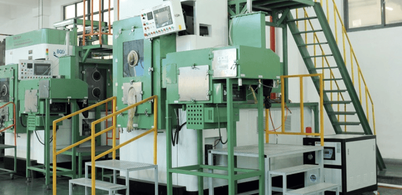
ENGINEERING SNAPSHOTKeep the requirement visible from review to release.
Critical geometry identified
Selected against the part
Fit and clearance included
Evidence stays with the feature
01 / FEATURES THAT NEED REVIEW
Make the critical feature visible.
Machining and wire cutting should be discussed around the faces, slots, edges, holes, profiles and tolerances that the assembly depends on.
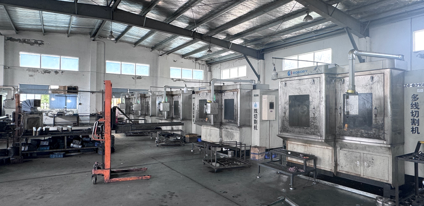
Reference faces
Identify the faces that establish the assembly datum.
Profile and slot
Show the feature and its relationship to the finished envelope.
Edge condition
Call out chamfers, radii or surface requirements.
Tolerance
Separate critical fit dimensions from general dimensions.
02 / MATERIAL AND GEOMETRY
The route follows the material and shape.
Sintered NdFeB geometry, coating allowance and magnetization requirements remain connected. The final route is confirmed against the approved drawing and production plan.
Material
Grade and finished condition remain project-specific.
Geometry
Shape and dimensions determine the machining review.
Coating allowance
Finish and fit should be considered together.
Orientation
Magnetization direction travels with the part requirement.
03 / INSPECTION BASIS
Inspect what the assembly depends on.
Dimensional evidence should focus on the feature that controls the fit. Surface, coating, magnetic direction and traceability can be added to the same release basis.
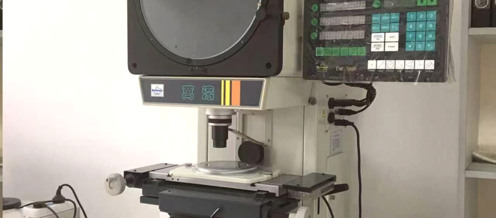
Critical dimensions
Measure the dimensions that control assembly.
Profile and position
Review features against the drawing references.
Surface
Keep finish and visual condition beside dimensional release.
Records
Agree the inspection and traceability basis.
04 / NEXT STEP
Bring the feature into engineering review.
Share the drawing or clear feature description, the mating context and the inspection priorities already known.
Feature
Identify the cut, face, edge or profile.
Fit
Explain the mating part and critical clearance.
Release
Add tolerance, coating and inspection needs.
MACHINING / WIRE / PROCESS BASIS
Start with the feature that matters.
A clear feature and fit context make the process review useful.
Discuss the Machined Feature